
The Apollo Missions. The Manhattan Project. Ford successfully beating out Ferrari at LeMans. There are certain engineering achievements in American history that have seemed almost super-human, inevitably ending up adapted for a blockbuster movie on the silver screen (see Apollo 13, Oppenheimer, Ford vs. Ferrari). But one American achievement that hasn’t received nearly enough credit is the development of the World War II Jeep, because when you dig into it, you’ll realize that, in a way, it was almost as unlikely as the three incredible feats I just mentioned and that you likely enjoyed along with a cup of soda and a bag of popcorn. Here’s what I mean.
An Undeniable Masterpiece That Inspired Every Iconic 4×4
The World War II Jeep — the subject of the extremely ambitious build I’m tackling thanks to our partners at eBay — is one of the auto industry’s greatest masterpieces. General George C. Marshall referred to it as “America’s greatest contribution to modern warfare.” Legendary WWII journalist Ernie Pyle once said: ““I don’t think we could continue the war without the jeep…It did everything. It went everywhere. Was a faithful as a dog, as strong as a mule, and as agile as a goat. It constantly carried twice what it was designed for and still kept going.” General Dwight D. Eisenhower said the Jeep was one of the most “vital” tools in the U.S.’s success in Europe and Africa.
![]()
But the Jeep isn’t just a masterpiece because it was an excellent tool for allied forces during WWII; the vehicle’s genius has been proven time and time again well after the war ended in the form of copycats. Just look at the world’s most legendary non-Jeep off-roaders: the Toyota Land Cruiser, the Land Rover, and the Ford Bronco.
Toyota has sold tens of millions of Land Cruisers over the years; Land Rover is a brand built entirely on off-road SUV offerings; and Ford calls the Bronco an “SUV Family,” with two Bronco vehicles selling in absurd quantities. And all three of these iconic brands owe their existence directly to the World War II Jeep.
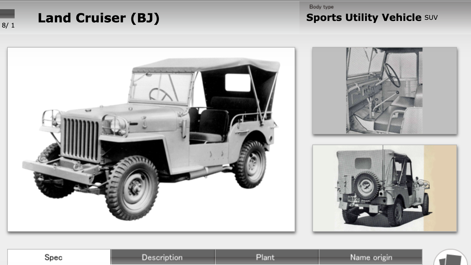
The very first Toyota Land Cruiser, shown above, was basically a carbon-copy of the WWII Jeep, with Toyota even referring to it as the “Toyota BJ Jeep,” but that name changed, with Toyota writing on its website: “As the Jeep name was a trade mark of Willys-Overland Motors, Toyota changed the vehicle name to the Land Cruiser in June 1954.”
Car culture website Silodrome says the original Toyota Land Cruiser came about when Toyota essentially reverse-engineered a leftover WWII Jeep, with the site writing:
The story of the Toyota Land Cruiser J Series (FJ40 / BJ40 etc) starts in the Philippines during the Second World War, the Japanese had invaded the nation, along which much of the rest of East Asia, and they found an abandoned Jeep that had been left by retreating American forces.
There is a little contention as to exactly which Jeep or Jeep-like vehicle it was that they found, most sources say it was either a Willys Jeep or a Ford GPW (Ford’s Jeep), but some claim it was an American Bantam BRC 60 Mark II.
Toyota themselves haven’t included any reference to this captured vehicle in their own history of the Land Cruiser, and instead pick up the story in the 1950s.
Whichever vehicle it was, we know that it was an American military 4×4, and we know the Japanese military immediately recognised how useful it would be to have their own version.
It was shipped back to Japan, and Toyota was tasked with building a local version using as many off the shelf parts as possible – they were also instructed to make sure it didn’t look too much like a Jeep.
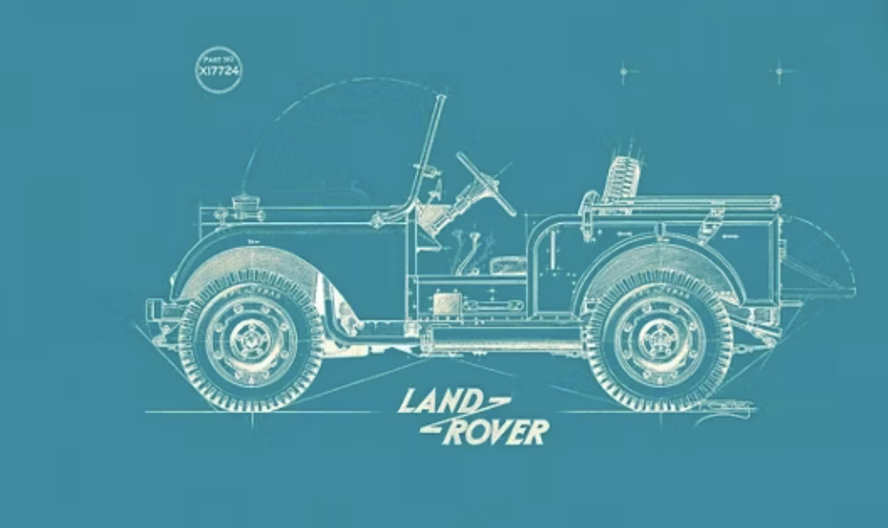
The Land Rover brand was also inspired by a WWII Jeep, and in fact, it began life as one, per Land Rover Sarasota:
Inspired by his own Jeep, Maurice Wilks began creating the very first designs of the Land Rover vehicle alongside his brother, Spencer at Newborough. In an attempt to fill a void in the markets, the design was created to include the Rover car engine and a Jeep chassis. The design originally featured the steering wheel in the center of the vehicle. This was done to make it suitable and convenient for both left and right-handed drivers.
The Land Rover was finally launched in [1948] at the Amsterdam Motor Show, where it was regarded as a huge success. Despite its British origin, they were a universal success, shipping to over 70 countries by the end of the year and to the U.S.A in 1949.
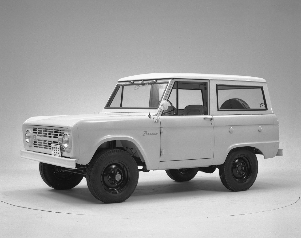
When Ford writes about the initial development of the Bronco, it leans into its WWII Jeep roots, since the company was one of two that built them (along with Willys-Overland):
Why and how did Ford develop the Bronco? For that story, we need to return to World War II. In addition to its other war-time production, Ford was one of three companies which worked to develop the Jeep. During the war, Ford produced more than 250,00 Jeeps and were renowned for their quality. After the war, surplus Jeeps were the choice of returning veterans and outdoor enthusiasts. However, with the improving highway system and demand for a more comfortable driving environment, even on the trails, Ford saw the chance to design and develop a best of class utility vehicle that could also serve as a sports vehicle. We already had experience building the Jeep, and during the late 1950s and early 1960s Ford designed and built the MUTT, a troop utility vehicle.
In 1962, Ford began to extensively survey Jeep and International Harvester Scout owners to see what they liked and disliked about their vehicles. These findings were summarized in an internal memo on July 11, 1963 noting that both vehicles had “poor comfort, ride, noise and vibration qualities” and that the size and power of both were also unsatisfactory. These findings, indicating a gap in the market, went to the Product Planning Committee on October, 23, 1963 with the recommendation for “funds for further development of a Ford utility vehicle, code named Bronco.” A fascinating memo a week later had the subject line “1966 G.O.A.T” as it heading. The G.O.A.T. terminology was indicative of the desire to develop a Goes Over All Terrain vehicle while the document itself describes the drivability of the car.
The list goes on and on. The Steyr Puch Haflinger, considered the greatest 4×4 by the 4×4 King of the World, Victor Ma, was Austria’s replacement for the WWII Jeep. The Nissan Patrol was inspired by the Jeep. One of the largest companies in India is Mahindra & Mahindra, with an annual revenue around $25 billion and over 300,000 employees around the world; where did the company gets its start? It received Knock-Down Kits (CKDs) of civilianized WWII Jeeps (CJ-2As) from the U.S., and simply assembled those vehicles in India. Mitsubishi also built its own WWII Jeep-inspired 4x4s in Japan, the Philippines has literally built its culture around WWII Jeeps (go into any Filipino store and you’ll see a toy “Jeepney,” which is an adapted WWII Jeep used as a bus).
Copied by many, beloved by all, the WWII Jeep was the undeniable beginning of the world’s 4×4 obsession.
80 Years Later, It’s Still The Perfect Formula
Before I get into the unbelievable story of how the WWII Jeep was developed, I just want to reinforce how masterful the design ended up being. I’ve already mentioned how it inspired the world’s 4x4s, but I’d also just like to point out how the Jeep’s basic formula remains pretty much perfect to this day.
As a car journalist, I often review four-wheel drive vehicles, and when I do, the first thing I mention is this: The most important attribute of a capable off-roader is favorable geometry. No lockers or low range gearing or tires can make up for lack of ground clearance or long overhangs. Geometry is king. From there, low-range gearing is important, as are tires, a “flexy” suspension that keeps the tires on the surface even when it’s uneven, underbody protection, traction aids like locking diffs, sway bar disconnects, low end torque, and on and on.
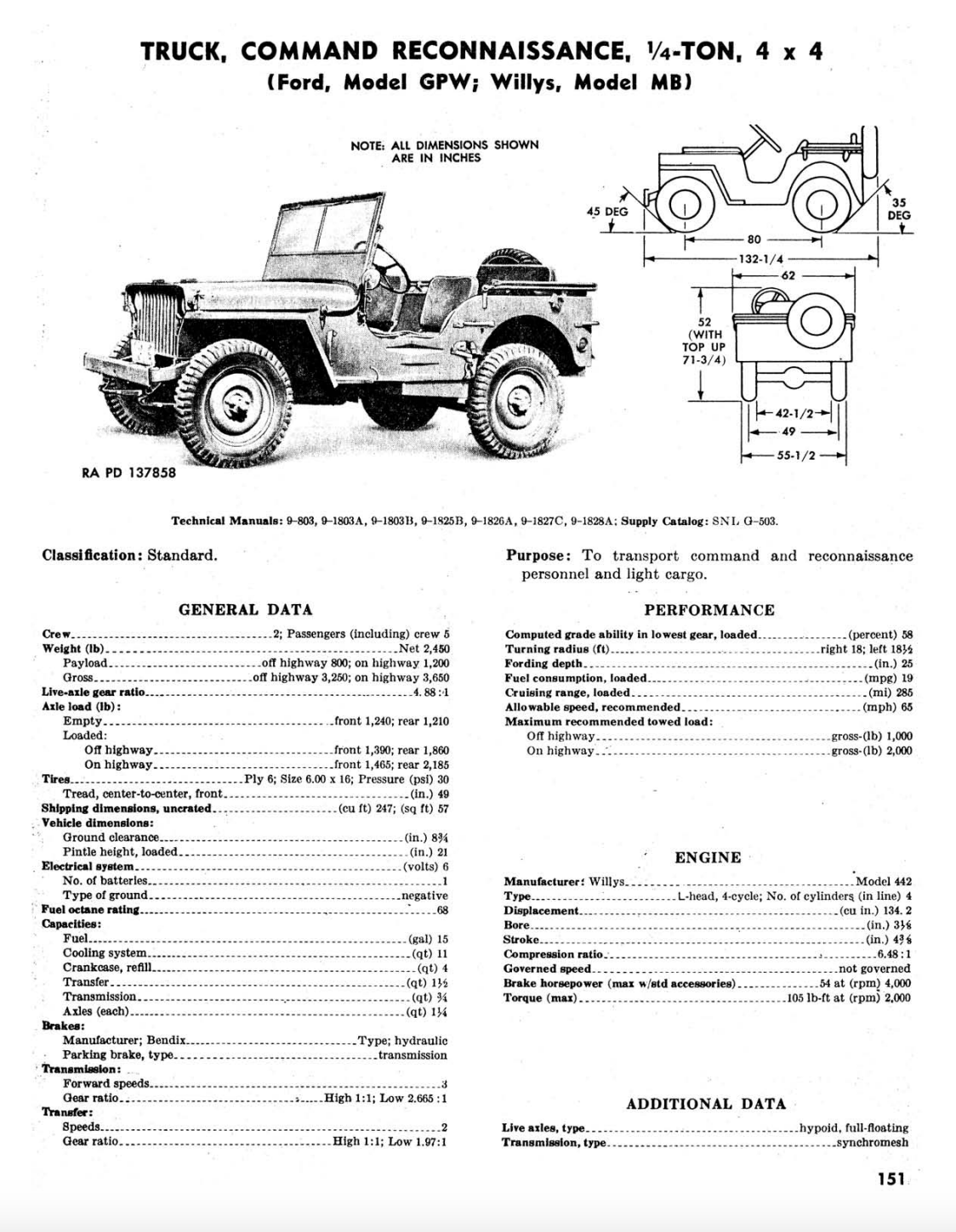
The WWII Jeep’s geometry remains phenomenal even in comparison to modern automobiles. Check out the datasheet above, and you’ll see an approach angle of 45 degrees and a departure angle of 35 degrees. While ground clearance is only about 8.75 inches, as I’ve written before, it’s the location of the ground clearance that has to be considered, and the WWII Jeep’s rocker panels and overhangs are way up high off the ground.
Let’s compare these figures to the two best off-roaders of today: The Ford Bronco Sasquatch and Jeep Wrangler Rubicon two-door have approach angles of 43.2 and the 44, respectively. While they both outdo the WWII Jeep when it comes to departure angle (43.2 and 37, respectively), the WWII Jeep wins in approach angle, which is the more important of the two figures, because getting the front wheels up on an object is a requirement to traverse it; you can often drag the belly or rear end whereas you can’t just ram the front bumper into an object.
Ground clearance is higher on the Wrangler and and Bronco, but that’s because they have absolutely gigantic tires, and while that can be an advantage, it can also be a huge disadvantage. With big tires, tall overhead valve engines (compared with the WWII Jeep’s low flathead motor), and just tall overall profiles, hillclimbs become sketchy unless you extend the wheelbase, which makes the vehicle larger and less maneuverable.
Speaking of larger, the WWII Jeep’s size is one of its biggest advantages. No, it doesn’t have the lockers or the disconnecting say bars or even the flexy coil spring suspension of the Wrangler and Bronco, but it makes up for those disadvantages with a small, flexy frame and just tiny dimensions, which are a huge deal when trying to snake through trees or boulders.
The two-door Jeep Wrangler is 35 inches longer, and the Bronco is 42 inches longer. Width wise, both are about a foot broader. And thanks to the Willys’ folding windshield and lack of a roll bar, it’s 20 inches shorter in height, allowing it to slither under fallen tree branches. As for curb weight, both the Bronco and Wrangler are over 1,500 pounds heavier.
Compare an 80 year-old sports car to a modern sports car, and the oldtimer will get left in the dust. But compare this 80 year-old legend to a modern off-roader, and the gap is surprisingly narrow. It’s proof that America got the formula correct on its first try.
Just watch how the WWII Jeep-based Willys CJ-2A outdoes a modern Mahindra Roxor during my comparison test:
And watch me drive a bone-stock CJ-2A (with slightly bigger tires) through the rocks of Moab, Utah:
A stock Wrangler Sport and stock Bronco Base would probably compare quite evenly off-road to a WWII Jeep, and while the higher trims, the Rubicon and Badlands, would probably leave a WWII Jeep behind in certain terrains, a modified WWII Jeep can hang with darn-near any vehicle out there. It’s a testament to the brilliance of that original platform, as demonstrated by Jeff Petrowich’s BAM BAM and Stan Fuller’s Grampa’s Jeep. Here’s BAM BAM doing crazy things:
And here’s the WWII Jeep king, Rick Pewe, showing off Grampa’s Jeep:
One Of The Greatest Feats In Automobile History
In order to achieve near-perfection on the first try, surely there were thousands of people working on the government’s 1940 request for proposal (RFP) for for a lightweight, troop-carrying 4×4 reconnaissance vehicle, right? Surely, like all those other achievements I mentioned, the full force of American engineering was working together towards this common mission, right?
No.
Only two companies responded to the government’s request, and the one that developed what would become the legendary WWII Jeep was a total underdog: a tiny company in Butler, Pennsylvania that was going through bankruptcy, again. That company was American Bantam, and before I give you some background on how this all went down, you need to know this: This small group of only 16-ish employees designed and built the off-road vehicle that would forever define the world’s off-roaders in a mere 49 days.
Forty-Nine Days.
It Seemed Like Destiny
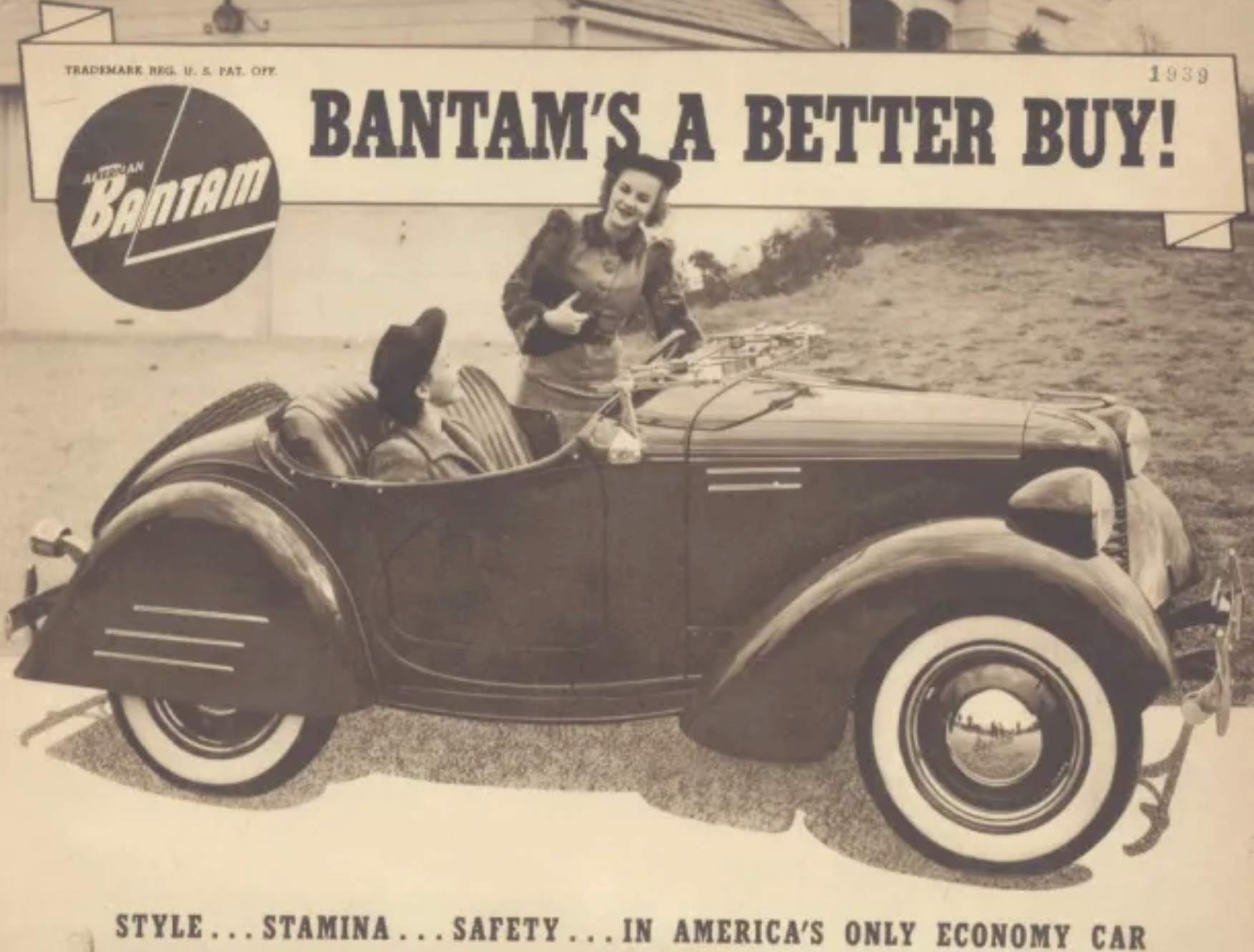
The improbability of this whole endeavor becomes astounding when you look at the history of American Bantam. Initially, the company was called American Austin, the U.S. division of the British car company Austin, which in 1922 had released its hot-selling Austin Seven, a small car that was a great fit for the U.K. and its struggling economy and high population density. It was, however, not a great fit for the U.S., which, like today, wasn’t so keen on tiny cars.
Nonetheless, Herbert Austin worked to sell his company’s Seven in the U.S., opening a factory in the former home of Standard Steel Car Company in Butler, Pennsylvania. As Paul R. Bruno writes in his book The First Jeep, Butler made a lot of sense, because it had a “forward-thinking business community and a workforce with the skills to manufacture cars.”
After the great depression, a small economy car like the Seven seemed like the perfect option, especially given how well the vehicle had been executed, as Bruno writes:
The vehicles delivered were masterpieces in small car engineering. The basic Austin specification of a 75-inch wheelbase, 40-inch tread, 122-and 53-inch length and width, 60.5-inch coupe height, 8.75-inch ground clearance with a total weight of 1,130 pounds were maintained [from the U.K. car] with American styling.
The American Austin Roadster was an affordable ($445) little car with an absurdly tight turning radius and dimensions much smaller than those of any other American car on sale. But nobody bought it. American Austin tried advertising the car as a secondary car for local driving, but this didn’t work, especially in a struggling economy; only just over 8,500 cars were sold in 1930, per Bruno.
American Austin then doubled down, offering more versions of the car; sales got even worse in 1931, and 1932 looked like the end. Then, per The First Jeep, a salesman named Roy S. Evans who had been excited about the small-car concept in the U.S. bought out the company, built the leftover stock of 1,500 cars and sold them for a rather reasonable $295, and did a bit of dealing with suppliers. He moved some more cars, but before long, American Austin Car Company was again headed into bankruptcy.
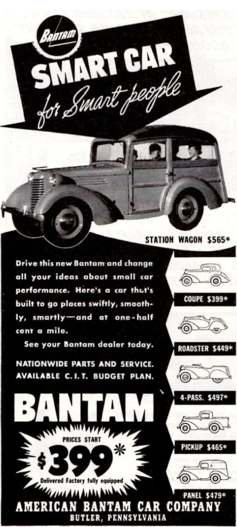
Evans didn’t give up, raising more money and rebranding the company with a nickname the diminutive vehicles had earned from the general public: Bantam. Thus, in 1937, American Austin Car Company became American Bantam Car Company. After working the then-new Reconstruction Finance Corporation and using a lien against the factory for more cash, American Bantam was back churning out cars, this time with more standardized off-the shelf parts. Harold Crist became the plant manager, and the vehicles were restyled, though another recession hit in 1938.
“The Bantam, thanks to Harold Crist and his team, was a state-of-the-art small car, and the little company in Butler, Pennsylvania was the unlikely, and singular depository of expertise on economy cars in the United States,” writes Bruno. Evans cut up the coupe to offer a new car, a convertible, but America just didn’t want tiny cars. “The firm had excellent, high quality products, which were state-of-the-art for small cars at the time, but nobody wanted them,” The First Jeep reads.
In 1939, the company sold just over 1200 vehicles, then down to 800 in 1940, and by June it was bankrupt again. But there was one last gasp for American Bantam: a military vehicle.
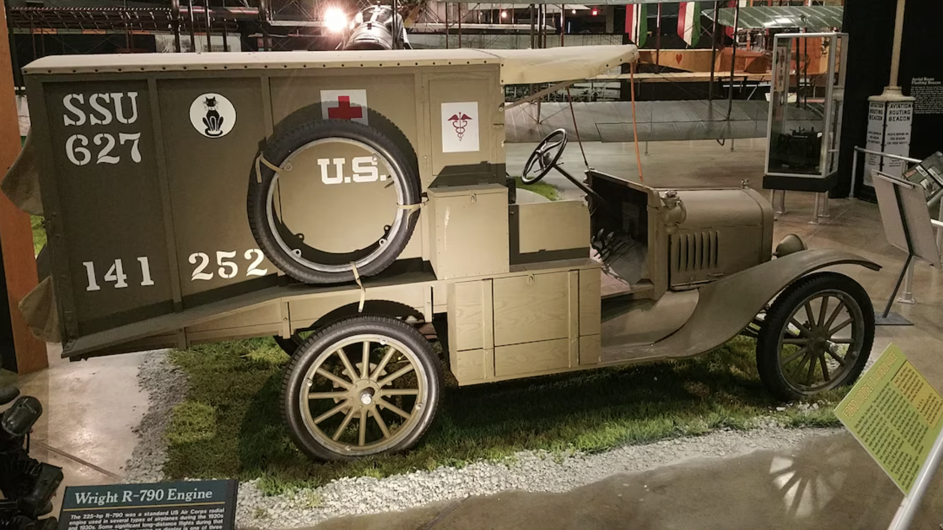
Everyone knew that by the 1930s warfare would be more mobile than the trench warfare of WWI. The military tested numerous tractors and 1/2 4×4 trucks including the Marmon Harrington (which the army was keen on), and it had developed out of junked American Austin parts a small scout car called the Howie Machine Gun Carrier. With a need for big payload to carry weapons for the infantry, but also the desire for a horse-like, stealthy reconnaissance vehicle for the artillery, it seemed like something between the 1/2 truck and the Howie Machine Gun Carrier (or the motorcycle+sidecar that the military had used up to that point) made sense. From The First Jeep:
“Development and testing during the latter half the 1930s had shown an adequate vehicle did not exist between the motorcycle and sidecar and the 1/2 ton 4×4 truck.”
American Bantam had sent a 1/2 truck for evaluation in the late 1930s (this was after the army had bought some American Austin Roadsters for testing in the early 1930s), but it wasn’t good enough. Bantam essentially apologized to the army and asked for another chance, but it was denied. Bantam’s leadership knew this was the only hope the company had to remain solvent, so it refused to give up. From Bruno’s book:
“[Bantam President Francis Fenn] knew that his company’s small cars were not selling, that by the beginning of 1940 the firm was bankrupt, and that producing an automobile for the Army was the only option left to save the company.”
What happened from here gets a bit murky, but there’s no doubt that a key player was Charles “Harry” Payne, a former naval aviator who became an ace salesman, and someone who had needed a good, small off-road vehicle when trying to rescue pilots being trained for an aircraft company he used to run. Per The First Jeep, Payne had been introduced to Bantam through someone at the Reconstruction Finance Committee, and was brought in to interface with aircraft companies keen to leverage Bantam’s manufacturing expertise to build aircraft parts.
As there was no Air Force at the time (it was the Army Air Corps), the assignment saw Payne interfacing with the U.S. Army. Here was a former-army, expert salesman who worked for the premier small-car company in the U.S. chatting regularly with the U.S. army, which had interest in a small reconnaissance vehicle. It was a perfect opportunity.
Here’s what Col. Oseth, who was in charge of “development of motor vehicles” for the Chief of Infantry Office said, per The First Jeep:
“I told Mr. Payne, in substance, this after we had definitely dismissed these other two vehicles, if you will take your bantam and put a front wheel drive, a front wheel driven front axle on it so as to make it four by four, strip the body down to the bare essentials and put power enough in there to keep those wheels turning, we will be willing to talk business with you, because that is what we are looking for. Mr. Payne said it was almost impossible…”
As I understand it, it was these meetings between Colonel Ingomar M. Oseth (whom Time Magazine called in a Nov. 1941 issue “The Army’s No. 1 jeep expert”) and Bantam’s Harry Payne that ultimately led to the establishment of detailed specs that would be sent out to over 130 automakers.
Development of those specs also involved a trip to Bantam’s factory, which was run by Harold Crist. Brian J. Duddy of the U.S. Department of Defense’s Defense Acquisition University (a Ft. Belvoir-based training school for the military) wrote in The Jeep at 70: A Defense Acquisition Success Story:
The details of the reconnaissance car specification drawn up by the Technical Committee were as follows: The 1 /4-ton vehicle had to have 4-wheel drive, a maximum weight of 1,200 pounds, a useful load of 600 pounds, a maximum height of 36 inches, and a wheelbase of 75 inches. The body style was to be rectangular with bucket seats and a fold-down windshield. Performance requirements included a minimum top speed of 50 mph and a minimum sustained speed of 3 mph.
As soon as the requirements were formalized, a small group of Army officers and civilians visited the Bantam factory in Butler, Pennsylvania, to further test Bantam vehicles and discuss the concept of the new military car with the Bantam development group (Denfeld & Fry, 1973; Rifkind, 1943). The results of this meeting allowed the Army to continue to refine the specifications and even sketch a rough outline of what the new vehicle should look like. Thus, by working with industry the Army had arrived at a set of requirements that was simple, functional—and most importantly—achievable (Denfeld & Fry, 1973).
On June 27, 1940, the Ordnance Technical Committee issued its final recommendations for a 1 /4-ton, 4×4 truck. (The term 4×4 meant the vehicle had four wheels, all of which were powered.) The vehicle maximum weight was now raised to 1,300 pounds with a 600-pound payload, and the wheel base was increased to 80 inches (Probst, 1976; Wells, 1946; Vanderveen, 1971; Denfeld & Fry, 1973). To keep the design simple, the Army intended for manufacturers to use several common pieces of military vehicle equipment already available such as tail lights and towing pintles. The Army sent invitations to bid on 70 “pilot” trucks or sample models to 135 manufacturers. Bidding instructions mandated that the first pilot model should be delivered to Camp Holabird in Baltimore in 49 days.
Only two automakers bothered answering the call, because what the Army was asking for was, frankly, impossible. Bantam, though, had no choice, and it also had a trick under its sleeve: Its new freelance designer, Karl Probst, simply ignored the weight spec. 1,300 pounds, in conjunction with the other specifications, was just not going to happen, and Bantam had enough engineering know-how to recognize that nobody else could pull it off. As Motor Trend wrote in a story that quotes the great Jeep historian Patrick R. Foster:
Bantam was confident no competitor would come close to the specification’s weight limit. Its own four-cylinder engine made half the 40-horsepower minimum, so Bantam fitted its entry with a 46-horse Continental four. Bantam won a contract for 70 vehicles, with a prototype to be delivered to the Army’s Camp Holabird, Maryland, proving grounds by September 23.
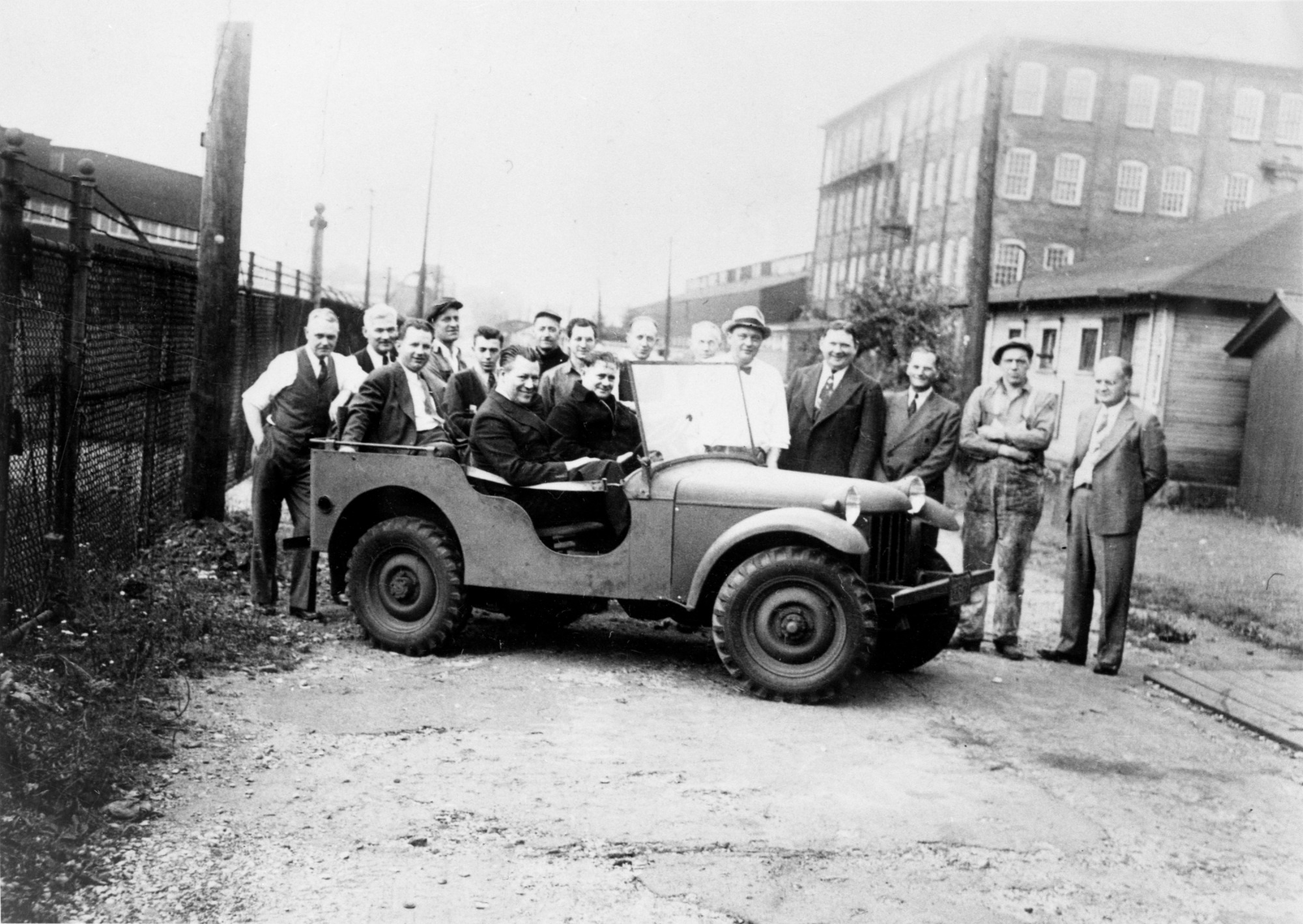
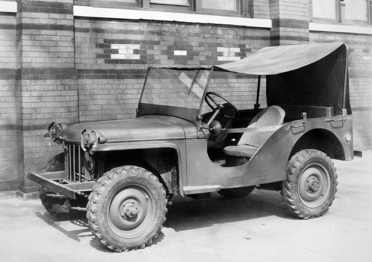
Bantam Reconnaissance Car #1, BRC, looked like the World War II Jeep we know, except for its curved hood and rounded front clip, not the flat pieces that would make the Jeep so easy to build and repair. It weighed 1,840 pounds, 570 more than the prescribed limit. Bantam delivered the prototype to Camp Holabird on September 22, where it performed beautifully before the eyes of the Quartermaster Corps, with Ford and Willys representatives also in attendance.
Developing an off-road icon in 49 days (and then having to make 69 remaining models within 75 days), whether you meet the weight requirement or not, is absurd. And it makes sense that the only two companies that responded to the bid, American Bantam and Willys-Overland, were struggling automakers that had expertise in small-car development and that offered a small four-cylinder engine.
Willys couldn’t pull off the ask, and was therefore out of contention, but American Bantam worked late into the night to meet the deadline, with Duddy writing:
Undaunted, [Bantam] pressed on with their design. Working around the clock, Bantam completed the prototype and company executives drove the vehicle directly from the factory in Butler to Camp Holabird, its first long-distance trip. On September 23, they made it through the gate at Holabird with only 30 minutes to spare on their 49-day deadline.
The Bantam vehicle, as delivered, weighed in at 1,840 pounds and was powered by a 45hp Continental engine. Since the vehicle was able to successfully complete a series of strenuous tests at Holabird, the Army representatives believed that the maximum weight target could be reconsidered.
[…]
Since it was extremely satisfied with the prototype, the Army gave the go-ahead to Bantam to initiate production of the other 70 pilot vehicles based on that design, but incorporating some design changes and improvements that resulted from the early testing of the prototype. These changes were to improve both performance and reliability.
The story from here is fairly well-known, and a bit sad. This scrappy little bankrupt, Butler, PA-based company had, against all odds, revolutionized not only warfare, but the auto industry at large, eventually inspiring every legendary 4×4 that would come after it. And it did it all in 49 days! But in the end, the U.S. Army handed over Bantam’s brilliant design to the competition, as Motor Trend writes:
“Much to the horror and surprise of the Bantam engineers,” Bernier writes in “Bantam’s jeep,” “Bob Brown, a civilian engineer for Holabird, provided the Willys and Ford representatives copies of Bantam’s blueprints and engineering data, as well as full access to the Bantam prototype car.” The Quartermaster, he writes, encouraged the two competitors to develop similar prototypes.
After tweaking BRC #1, the Army ordered 500 reconnaissance cars each from Bantam, Willys, and Ford. Bantam protested, and the Quartermaster Corps explained that there was a shortage of constant velocity joints from its supplier. Spicer Manufacturing required orders for 1500 vehicles to justify mass-production tooling.
The Army eventually revised its weight requirements, with the full spec sheet at the bottom of this article. In the end, almost every single WWII Jeep was built by either Willys-Overland or Ford Motor Company, firms that the U.S. government believed had better likelihood of quickly manufacturing hundreds of thousands of Jeeps. Bantam built utility trailers for the Jeeps, as well as other wartime instruments.
The scrappy team had changed the world forever with a true engineering masterpiece — a game-changer by all metrics. But it would be one that Bantam would never mass-produce, and one that wouldn’t save it from its 1956 demise.
¼ ton 4×4 Specs Sent To 135 Companies:
C. SERVICE REQUIREMENTS.
C-1. General. The trucks described in this specification are intended for use as tactical trucks by the United States Army. They will be required to transport the rated payload, which consists of military supplies, equipment and personnel, at relatively high rates of speed over all typos of roads, trails, open and rolling cross country, under all conditions of weather and terrain, while at times towing a trailed load, such as a 37mm anti-tank gun, and all units and assemblies in the truck must be suitable for such use. Any design which renders servicing, adjustment and replacement unduly difficult under field conditions, is not acceptable.
C-2. Abilities. The truck, fully equipped and loaded, shall demonstrate the following abilities on smooth concrete roadway:
a. Speeds.
(1) A level road maximum speed of not less than fifty-five (55) miles per hour, at an engine speed that does not exceed the peak horsepower speed.
(2) A level road minimum speed of not more than three (3) miles per hour, at engine full torque.
b. An ability to ford (hard bottom) water crossings of at least eighteen (18) inches (water) depth, at a truck speed of at least three (3) miles per hour, without water objectionably entering any chassis unit or seriously affecting engine operation, this with cooling fan operating.
C-3. Traction Devices.
a. Tire chains are required for use on driving wheel tires, and frequently will be used when traversing hazardous terrain. The truck construction shall permit the, satisfactory installation and use of the tire chains.
D. SPECIFICATIONS.
D-1. Chassis.
a. Weights and Loads.
(1) The weight of the truck, fully equipped (including lubricants and water), but less fuel, tire chains and payload, shall not exceed twenty-one hundred (2100) pounds for two (2) wheel steer trucks, and twenty-one hundred and seventy-five (2175) pounds for four (4) wheel steer trucks, and every effort, consistent with best recognized engineering practices, shall be made to minimize the weight.
(2) The payload allowance shall be eight hundred (800) pounds, for operating personnel (including the driver) and military supplies.
(3) The truck maximum gross weight shall be the minimum consistent with the sturdiness required by the service conditions and, where a requirement in this specification stipulates that the truck shall be fully equipped and loaded, it shall include the weight of the truck completely equipped, including fuel, lubricants, water, tire chains, and payload. Gross weight distribution shall minimize tire overloading,
(4) The towed Load will be one thousand (1,000) pounds gross weight, and will be mounted on two (2) pneumatic tire equipped wheels.
b. Dimensions. The angle of approach shall be at least forty-five (45) degrees; angle of (departure at least thirty-five (35) degrees, with the truck fully equipped, loaded, and in a level. position. Ground clearance under all portions of the chassis below the frame shall be sufficient to permit operation over unimproved road, trails and open, rolling and hilly cross country without interference with the terrain, not less than nine and one-half (9-1/2) inches other than under the axles, and not less than eight (8) inches under the axles, each with truck fully loaded. If the ground clearance offered, other than under the axles, is less than deemed necessary, the right is reserved to require that it shall be properly increased, without additional cost to the Government. The wheelbase shall be not more than eighty (80) inches. The design of the cowl, engine hood and radiator shall provide for the driver the maximum visibility practicable. The height of silhouette (body proper, cowl an hood) shall be the minimum practicable, not more than forty (40) inches with truck fully equipped and loaded. Overall height and body floor height above ground, minimum practicable.
c. Flexibility. With the truck fully equipped and loaded, tire chains installed on front and rear wheels, and the front wheels cramped at any angle (rear wheels also cramped on four wheel steer truck), the truck construction shall permit eight (8) inch high blocks being placed under two (2) diagonally opposite wheels without part failure or interferences occurring.
D-2. Frame. The chassis frame shall be of such design and construction as to support adequately the maximum gross loads and maintain necessary chassis alignment and stability under the most severe operating conditions. The frame shall be properly braced for pintle mounting.
D-3. Power Unit. The power unit shall consist of an engine, clutch and transmission embodied in a unit power plant. The engine mounting shall be guaranteed to be effective in eliminating strains resulting from frame distortion. The transfer case may be unit with the transmission, or may be a separate unit independently mounted, provided that the unit is properly mounted. Transfer case mounting bolts on separate unit mounting, shall include cotter pins, or the heads shall be effectively locked.
D-4. Engine. The engine shall be of the internal-combustion, four-stroke cycle type, having not less than four (4) cylinders. Piston displacement shall be not less than one hundred and ton (110) cubic inches and, less only fan and generator operating, the engine shall develop not less than eighty (80) pounds-feet torque, with a compression ratio suitable for use with fuel having a knock rating of not more than seventy-two (72) octane number. The peak horsepower speed shall be sufficient to enable the truck, fully equipped and loaded, to demonstrate definitely by actual test, compliance with the ability factors specified in Paragraph C-2.a. herein. The crankshaft shall be statically and dynamically balanced and supported by not less than three (3) main bearings. Cylinder heads shall not be made of aluminum. Manifold manual hot-spot mechanism, if provided, shall have its operating positions clearly inscribed. Automatic hot-spot heat control may be furnished when approved by the Purchasing and Contracting Officer. The engine shall be tapped for 14 mm or for 10 mm spark plugs. Oil pan drain plug shall conform to Q.M. Drawing 08636-V. Oil pressure gauge connection, preferably, shall be standard one-eighth (l/8) inch pipe tap. Carburetor fuel inlet connection shall be standard one-eighth (1/8) inch pipe tap. Water jacket drain shall be standard one quarter (1/4) inch or three-eighth (3/8) inch pipe tap size, with Weatherhead #1415 or #270 (or equal) drain cock. Water temperature gauge connection in engine shall be standard one-half (1/2) inch pipe tap. Oil filler tube cap and crankcase breather tube cap, if removable for engine servicing purposes, shall be fastened to the engine by a chain on other suitable means. To prevent stones damaging the engine oil pan, a metal plate shall be provided under the oil pan, the plate stock thickness to be at least #12-U.S.S. Gauge.
D-5. Cooling System. Paragraph D-5, Federal Specification KKK-T-706 applies. The system shall be capable of maintaining a differential in temperature, between the radiator inlet (Engine outlet) water temperature and air temperature, of not to exceed one hundred thirty (130) degrees Fahrenheit as measured on a vehicle dynamometer at full engine torque speed. A thermostat shall be provided in the cooling system. The radiator core shall be of the tubular type and so mounted that it will not be damaged by frame distortion. Counterflow of heated air to the front of the radiator from the engine compartment shall be effectively prevented. Radiator drain shall be standard one-quarter (1/4) inch or three-eighths (3/8) inch pipe tap size, with Weatherhead #145 or #270 (or equal) drain cock so positioned that it will not be opened or damaged by contacting brush. The radiator filler shall conform to Q.M. Drawing 08593-W, equipped with pressure type cap. The fan design, mounting and drive shall be consistent with the sturdiness, efficiency and quietness required by the service conditions. It shall be possible to quickly remove, install and adjust the fan belt, this to facilitate the fording of water crossings of a depth greater than eighteen (18) inches. A substantial metal shield shall be provided under the fan driving pulley and bolt, arranged to effectively prevent brush and stones damaging the pulley and belt.
D-6. Lubrication System
a. The engine lubrication system shall be in accordance with best commercial practice, and the system shall function satisfactorily on side slopes up to forty (40) per cent, and on longitudinal slopes to sixty (60) per cent.
b. An oil filter conforming to Q.M. Specification ES-No. 565 shall be provided.
c. A flexible line conforming to Q.M. Specification ES-No. 495 shall be provided from the engine to the oil pressure gauge. The crank case oil filler shall be so constructed that oil can be poured from a one (1) gallon approved container into the filler opening without requiring the use of a funnel and with only the hood raised. The crank case oil bayonet gauge finger loop shall be properly accessible.
d. The chassis lubricating system shall be of the high pressure type, with hydraulic type fittings located in accordance with & best commercial practice. The fittings shall be of a design that will permit proper attachment of the grease gun.
D-7. Ignition System. The engine shall be equipped with a complete battery-generator ignition system. Spark advance mechanism shall be of the semi-automatic (with manual advance mechanism) or effective automatic type. Manual advance mechanism, when provided, shall be so constructed and mounted that it is readily operatable from the driver’s seat. The ignition switch shall conform to Q.M. Drawing 08674-W. The distributor and coil shall be types to be approved by the Purchasing and Contracting Officer. Ignition suppression shall be provided conforming to Q.M. Specification ES-No. 603.
D-8. Fuel System. The fuel system shall consist of. One (1) gasoline tank, having a capacity of not less than fifteen (15) gallons, including baffles properly secured in place, the tank to be mounted under the driver’s seat cushion. Tank filler to be located approximately at the center of the top of the tank, to conform to Q.M. Drawing 08592-V, and equipped with pressure cap and chain. The tank drain plug to be standard one-quarter (1/4) inch or three-eighths (3/8) inch pipe tap size. Mechanically operated fuel pump including strainer, metal sediment bowl and hand primer, pump to be AC Model #1537714 (except as to rocker arm), hand primer to be accessible. Auxiliary fuel filter conforming to Q.M. Drawing 08366-W, imposed in the fuel line between the fuel tank and fuel pump, so located on the chassis that it can be serviced readily by one (1) man without requiring the removal of surrounding material and, unless mounted at a point higher than the fuel tank, to include a suitable shut-off valve in the inlet line to the filter. Air cleaner of the oil bath type, having sufficient oil capacity and volume to deposit one (1) pound of dirt and maintain an efficiency of at least ninety-seven (97) per cent, designed for high angle operation, and so mounted that mud and water will not enter the air inlet opening. Solid wall fuel lines shall be five-sixteenths (5/16) inch size tubing equipped with inverted flared type fittings. The fuel line connection to the tank shall be so located that it will not be readily damaged. A flexible fuel line shall be provided from the fuel line on the frame to the fuel pump; in addition, flexible lines shall be provided at every point where vibration might cause tubing failure. Flexible tubing shall conform to Q.M. Specification ES-No. 495. The fuel pump and lines shall be so arranged that vapor lock is effectively prevented. Fuel lines shall be located in a protected position, properly clipped to the chassis, and metal protective loom must be provided on the fuel lines at all points where the lines pass through metal members. The fuel system shall function satisfactorily on side slopes up to forty (40) per cent and on longitudinal slopes to sixty (60) per cent.
D-9. Exhaust System. A substantial leak-proof exhaust system, amply proportioned and securely mounted shall be provided. The tailpipe shall discharge into the slip stream of the rear tire, in such a manner as-to-effectively preclude the entrance of fumes into the body, undue heating of tires and disturbance of road dust.
D-10. Clutch. The clutch shall have a torque capacity at least equal to the maximum (gross) torque developed by the engine. Except where it is the truck manufacturer’s practice to furnish the clutch throwout bearing grease packed for the life of the truck, a lubrication fitting shall be provided, for the throwout bearing, at a readily accessible location which does not require the removal of floor or toe boards.
D-11. Transmission. Shall be of the three (3) forward and one (1) reverse speed type, with direct drive in third (3rd) gear. The low gear reduction shall be at least 2.9 to 1.0. Gears shall be heat-treated and properly finished to insure quiet operation. Input torque capacity shall to at least equal to the engine maximum (gross) torque.
D-12. Transfer Case. Shall be of the two (2) speed type having a high range ratio of 1.0 and low range reduction of approximately 2.0 to 1.0. The case shall include front axle drive declutching mechanism. Input torque capacity shall be guaranteed to be ample to transmit the maximum (gross) torque of the engine as developed through the lowest gear reduction provided in the transmission. Gears shall be heat-treated and properly finished to insure quiet operation. Separate control handles shall be provided for shifting the range gearing and declutching mechanism, with simple means provided that will prevent low range gearing being utilized when the front axle drive is disengaged.
a. An S.A.E. power take-off aperture shall be provided on the transfer case at the rear end of the top (main) shaft, so designed that commercially obtainable power take-off mechanism can be properly installed without requiring machining of transfer case parts or disassembly Of the case. The design of the case shall permit power take-off operation both with the truck moving and at a standstill.
b. A substantial metal skid shoe shall be provided under the transmission and transfer case, to prevent stones damaging the unit cases.
D-13. Propeller Shaft. The combined torque capacity of the front and rear propeller shafts shall be at least equal to the maximum (gross) torque of the engine, as developed through the lowest intervening gear reductions. If a propeller shaft is provided between the transmission and transfer case, its torque capacity shall be at least equal to the maximum (gross) torque of the engine as developed through the lowest gear reduction provided in the transmission. Universal joints shall be of the same make and type, of latest design and metal construction through out, and shall be guaranteed to function satisfactorily under continuous operation at the angles that will prevail with the truck in the fully’ equipped, loaded and level position, and for momentary operation up to the maximum angle that will prevail. Propeller shaft lengths shall conform to unit manufacturer’s recommendations.
D-14. Axles. The front and rear axles shall be of the full floating type, of such construction that in the event of an axle shaft failure, at any point, the wheel will not be released. Axle reduction gearing shall be located in the axle housing bowl and ratios shall be perfectly matched between front and rear axles. The axle ratio shall be not less than 4.75 to 1.0, Axle shafts shall be not less than one and one-eighth (1-1/8) inches in diameter over the splines in the differential. The ratio of impact resistance between the horizontal and vertical planes of the axle housing shall be suitable for the use indicated by the service requirements of this specification. If breathers are provided in the axle housings, they shall effectively prevent the entrance of water when the axle is submerged. Gear lubricant shall be positively confined to the differential bowl. Axle shaft flanges all shall be tapped for puller screws, tapped holes all to be the same size; puller screws to be furnished in rear axle flanges. The combined input torque capacity of the two (2) axles shall be at least equal to the maximum (gross) torque of the engine as developed through the lowest intervening gear reductions. The front axle shall be equipped with steering drive ends that include constant velocity universal joints having an outside spherical diameter not less than three and one-quarter (3-1/4) inches. Steering pivots shall be equipped with approved type bearings, with suitable means for adjustment. The offset between the king-pin center and tire center, at the ground, shall not exceed two (2) inches. Steering end bell packings shall include spring steel expanders. The front wheel cramping angle shall be at least twenty-six (26) degrees at the wheel on the inside of the turning circle. When axle stops have been adjusted to provide a maximum cramping angle of twenty-six (26) degrees (plus zero (0) degrees, minus one (1) degree) they shall be so welded that the angle adjustment can not readily be altered. Axle stops shall be so designed that they positively limit the cramping angle to the maximum angle intended by the stop adjustment. Hubs shall not include provisions for lubricating fittings. The steering tie rod shall be at least one and one-eighth (1-1/8) inches outside diameter steel bar stock, heat-treated, and its ends shall be so threaded that a fine toe-in adjustment is permitted. The rod shall be fully protected from damage, Axle bowl cover plates, when used, shall be bolted to the housing. The strength and stock thickness of the cover shall be equal to that of the housing. It shall be possible to remove all wheel bearings without having to remove snap rings.
a. When the Invitation for Bids requires that the truck shall be of the four (4) wheel steer type, the rear axle shall be equipped with steering drive ends identical to those furnished on the front axle, this to provide for four (4) wheel steering on the truck.
D-15. Springs. Clearance between the springs and spring stops shall prevent any frequent objectionable bottoming, and front spring stops hall prevent any possibility of the front axle and front propeller shaft striking the engine oil pan, under all conditions of operation including one where the moving loaded truck front axle encounters an obstacle or drops into a hole while the brakes are simultaneously applied, and operation where the trailed load is being towed with its brakes inoperative. Springs shall have at least two (2) spring leaf clips provided each side of the center bolt, properly spaced to prevent fanning of the leaves. Spring arch shall be minimized; filler blocks between axles and springs shall be limited to the usual spring seats.
D-16. Shock Absorbers. Hydraulic shock absorbers, of adequate capacity, shall be furnished on both axles, mounted at each side of the frame.
D-17. Bogie. Does not apply.
D-18. Wheels and Tires.
a. Wheels, mounting studs and nuts shall conform to Q.M. Drawing 08795-Y.
b. Tires, size 6.00-16, 4-ply, conforming to Federal Specification ZZ-T-381, shall be balloon, mud and snow tread type. Tread design to be submitted for approval by the Purchasing and Contracting Officer. Inner tubes shall be of the heavy duty type, conforming to Federal Specification ZZ-T-721. The tire, tube and flap shall be balanced within forty (40) inch-ounces, Tires shall have a permanent balance mark on the side wall on the valve stem side. The wheels, hubs and drums shall be suitably balanced.
c. One (1) spare wheel, tire and tube assembly shall be furnished with each truck, properly mounted at the rear of the body.
d. The truck, including the wheels and rims, shall be suitable for use with inner tubes of the approved bullet sealing type conforming to Rock Island Arsenal Specification RIXS-114, regardless of whether or not bullet sealing inner tubes are required to be furnished.
D-19. Brakes. The truck shall be equipped with a braking system that will safely control the fully equipped and loaded truck under all operating conditions; the system shall be complete with every necessary piece of equipment and the mechanism shall readily be accessible to external adjustment.
a. Service Brakes. The service brake system shall be of the hydraulic application type. Brakes and drums shall be provided on all wheels. The drums shall have flanges or ribbing that prevents objectionable distortion when the brake is applied. The system provided shall be of a braking capacity sufficient to control and hold the fully equipped and loaded truck (without towed load) while traveling on a sixty (60) per cent grade, and bring it to a complete stop at a rate of deceleration equivalent to a stop within twenty-five (25) feet from a speed of twenty (20) miles per hour on a dry, hard approximately level road, free from loose material, at a brake pedal pressure not to exceed one hundred and twenty-five (125) pounds. There shall be no evidence of excessive fading. The master cylinder shall be of the compensating type with self-contained fluid reservoir, and wheel cylinders shall be provided at every wheel. Hydraulic line maximum pressures shall not exceed hydraulic brake manufacturer’s recommendations. Brake lines must be securely anchored to the chassis, adequately protected from damage and frame to axle brake flexible lines shall be designed and installed in a manner to be approved by the Purchasing and Contracting Officer. Metal protective loom must be provided at all points where the lines pass through metal members. The hydraulic stop light switch shall conform to Q.M. Drawing 08773-V.
b. Parking Brake. The parking brake or brakes, shall be hand lever operated, provided in addition to the service brakes or entirely separate mechanical operating mechanism connected to the service brake shoes. The system shall be capable of controlling and holding the fully equipped and loaded truck (without towed load) while traveling on a sixty (60) per cent grade. When the parking brake is so mounted that it is applied on the propeller shaft, it shall be located in such a position as to be operatable at all times on the rear wheels.
D-20. Electrical Equipment. Paragraph D-20, Federal Specification KKK-T-706 applies, unless otherwise specified. The system shall be of six (6) volt potential.
a. A storage battery shall be provided conforming to Q.M. Specification ES-No. 512. The battery negative terminal shall be grounded to the chassis.
b. The generator and starting motor shall be off adequate capacity, properly mounted, and effectively protected from exhaust heat. Generator operating speed shall not exceed 5100 r.p.m. at the engine peak horsepower speed. The generator shall be of the shunt type, with integral ventilating fan. Generator regulation shall consist of an apparatus box containing a cut-out relay, voltage regulator unit and current regulator unit. The current regulator unit shall be set to limit the generator output to the maximum output guaranteed by the generator manufacturer. The apparatus box shall be substantially constructed, dust-proof, and suitably mounted. The generator and apparatus box shall be of the same make. The generator, apparatus box and starting motor, including pinion meshing device or over-running clutch, shall be types to be approved by the Purchasing and Contracting Officer. The starting switch shall be suitably located.
c. Wiring shall be properly installed, shall include terminals soldered to the wire ends and junction blocks shall be provided having Bakelite (or equal) bases equipped with brass or properly rust-proofed steel bolts, washers and nuts for the attachment of wire end terminals. Wiring shall include distinctive colored tracers or metal identification tags. Wires in conduits shall be thoroughly insulated from metal conduits. When junction blocks are installed at locations where they probably will be coated with mud or water soaked, the blocks shall be properly covered. A main junction block shall be mounted on the dash in such a manner that all wiring to the dash can be disconnected from the junction block.
D-21. Chassis Equipment. The chassis equipment shall be complete, including at least the following enumerated articles:
a. Engine hood, brush guard, front fenders, short running boards, sturdy front bumper and rear bumperettes, conforming to Q.M. Drawing 08825-Z. The bumpers to be mounted at such heights that the front bumper will overlap by at least three (3) inches the rear bumperettes on a similar truck, with the trucks loaded and unloaded and on level ground; rear bumperettes not to interfere with the use of the rear pintle; front and rear bumpers to be bolted to the chassis.
b. Instrument board. Shall include speedometer, ammeter, fuel, temperature, and oil pressure gauges, conforming to Q.M. Drawing 08677-Y, Ignition and light switches, carburetor choke, hand throttle and, when provided, manual spark control, shall be arranged generally as shown on Q.M. Drawing 08660-X.
c. Tool Equipment. The tool equipment shall conform to Motor Vehicle Tool Set Type I as specified in Q.M. Specification ES-No. 422. Chains, four, (4) of Type D (extra heavy truck type chains) required. Provisions shall be made for the use of the starting crank.
d. Accessory Equipment. The accessory equipment shall be complete, including at least: One (1) rear view mirror substantially mounted at the left side on the outside of the body, mirror to conform to Q.M. Drawing 08634-X. Two (2) separate windshield wipers of the hand operated type, suitably installed on the windshield. Locks, Code H-700 key operated type, provided in the ignition switch on spare tire carrier, and on tool storage compartment; keys in triplicate with each truck; padlocks (where used) to be one and one-half (1-1/2) inch size, with hardened steel shackles, chained to chassis; during shipment keys furbished with each truck to be inclosed in a substantial cloth bag and wired securely to the chassis steering wheel. Electric horn end mounting, conforming to- Q.M. Drawing 08641-W.
e. Lighting Equipment.
(1) The lighting equipment shall all be of the best commercial grade.
(2) Two (2) head lamps shall be furnished of the five (5) inch Sealed Beam type having an upper driving beam and a lower traffic beam. The filaments shall be rated at forty (40) watts (minimum) for the driving beam and thirty (30) watts (minimum) for the traffic beam. Suitably approved means shall be provided for aiming the head lamp beams, and head lamps shall be mounted as low as possible.
(3) The wiring and lighting system shall conform fully to Q.M. Drawing 08675-X, (Trailer lighting socket not required.)
(4) Reflector Equipment. Reflectors complying with Q.M. Drawing 08642-W shall be suitably mounted at protected positions on the body as follows:
Four (4) Red Reflectors shall be mounted on the lower rear corners of the body, two (2) visible from the sides and two (2) visible from the rear.
D-22. Controlling Mechanism. Paragraph D-22, Federal Specification KKK-T-706 applies. The steering wheel diameter shall be not less than fifteen (15) inches. At least two and one-half (2-1/2) inches clearance shall be provided between the outer edge of the steering wheel and nearest projection. The column shall be attached to the instrument board by means of a substantial bracket that includes rubber insert. The gear housing shall be attached properly to the frame.
a. When required by the Invitation for bids, the truck shall be of the four (4) wheel steer type with suitable delayed steering on the rear wheels. The design of the steering mechanism shall preclude and tendency to over-steer due to too rapid steering action, end there shall be no noticeable weaving of the rear end of the truck. Steering mechanism design shall be approved by the Purchasing and Contracting Officer.
D-23. Operating Mechanism. Paragraph D-23, Federal Specification KKK-T-706 applies. The mechanism shall be so located that it does not detract from the comfort of the occupants. The accelerator pedal shall be a type on which the whole (driver’s) shoe rests, shall be so located to the right of the brake pedal that it can be comfortably used for long periods of time, and shall include a foot rest. The transmission and transfer case shift handles and hand brake lever shall be located at the center of the driver’s compartment.
D-24. Name, Caution and Shifting Plates.
a. Name Plate. A name plate shall be mounted on the truck, bearing the following data:
Nomenclature: Truck, 1/4-Ton, 4×4.
Supply Arm or Service
Maintaining Vehicle: Quartermaster Corps
Make and Model:
Serial Number : (Manufacturer’s Number)
Gross Weight: (Including 800 lbs. Payload, fuel and tire chains)
Maximum Payload: 800 lbs.
Maximum Trailed Load: 1000 lbs.
Date of Delivery:
Recommended by Manufacturer:
Octane Rating of Gasoline:
S.A.E. Grade of Oil for Summer Use:
S.A.E. Grade of Oil for Winter Use:b. Caution Plates. Plates shall be installed on the truck on which shall appear the maximum road speeds permissible in every gear range, and specific data concerning draining of the cooling system.
c. Shifting Plate. A plate shall be mounted on the truck on which shall clearly appear data concerning transmission, transfer case range gear and declutching mechanism shift handle operating positions, and the statement: “Disengage Front Axle Drive When Operating On Dry Hard Surfaced Roads.”
d. Plates shall be metal with black background; and drawing of the plate and mounting locations shall he approved by the Purchasing and Contracting Officer, before the plates are manufactured and installed.
D-25. Body
a. The body shall conform to Q.M. Drawing 08825-Z.
D-26. Special Operating Equipment. Shall include: Rear pintle conforming to Q.M. Drawing 08783-X. Towing hooks mounted at the front of the truck, or the front bumper to be so designed and mounted that it can be used for the attachment of a tow rope or tow bar and without sharp edges that will cut a tow rope. Pedestal mount base conforming to Q.M. Drawing 08825-Z. Shovel and axe brackets, mounted on the side of the body. Canvas covers for windshield and headlamps.
D-27. Painting And Marking. Shall conform to Q.M. Specifications ES-No. 474 and ES-No. 510 (Color blue-drab).
E. TEST REQUIREMENTS.
E-1. Tests preliminary to acceptance of the completed trucks furnished in accordance with this specification will be made at the plant of the truck producer or at a location approved by the Purchasing and Contracting Officer. The tests will be conducted by or under the supervision of the authorized Government inspector and shall consist of such tests as are necessary to determine compliance with this specification. Any or all of the trucks may be tested, and the truck producer shall provide without expense to the Government, the necessary fuel and other operating supplies required to accomplish them.
E-2. Unless otherwise specified in the Invitation of Bids, two (2) pilot model trucks will be produced and made available for test at the Holabird Quartermaster Depot, in conformity with Paragraph E-7.a. of Q.M. Specification ES-No. 459.
[Ed Note: David mentioned the idea of building a brand new WWII Jeep to the team at eBay, and they loved the idea so much they said, “How can we help?” Their financial support and David’s Jeep-obsession are the fuel behind this crazy build.]
Top Image: US Department of War